Procedure.
To perform the setup of the device from factory settings, we must connect via Ethernet wire (connected from the LAN port to the PC) or through the default WI-FI network. This can be validated on the rear label of the Teltonika device.
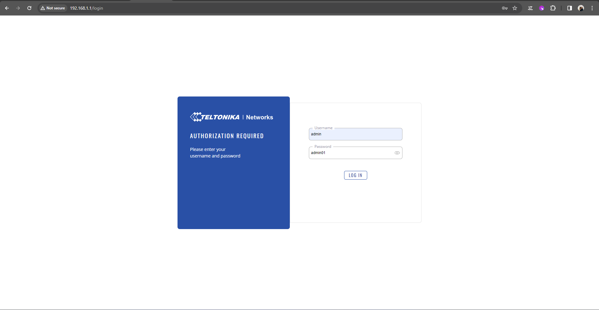
Step 1. Access the following link http://192.168.1.1/login with the following credentials:
1. User: admin.
2. Password: admin01.
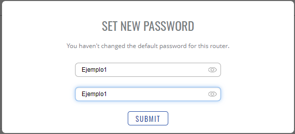
Now, change the password for the admin user.
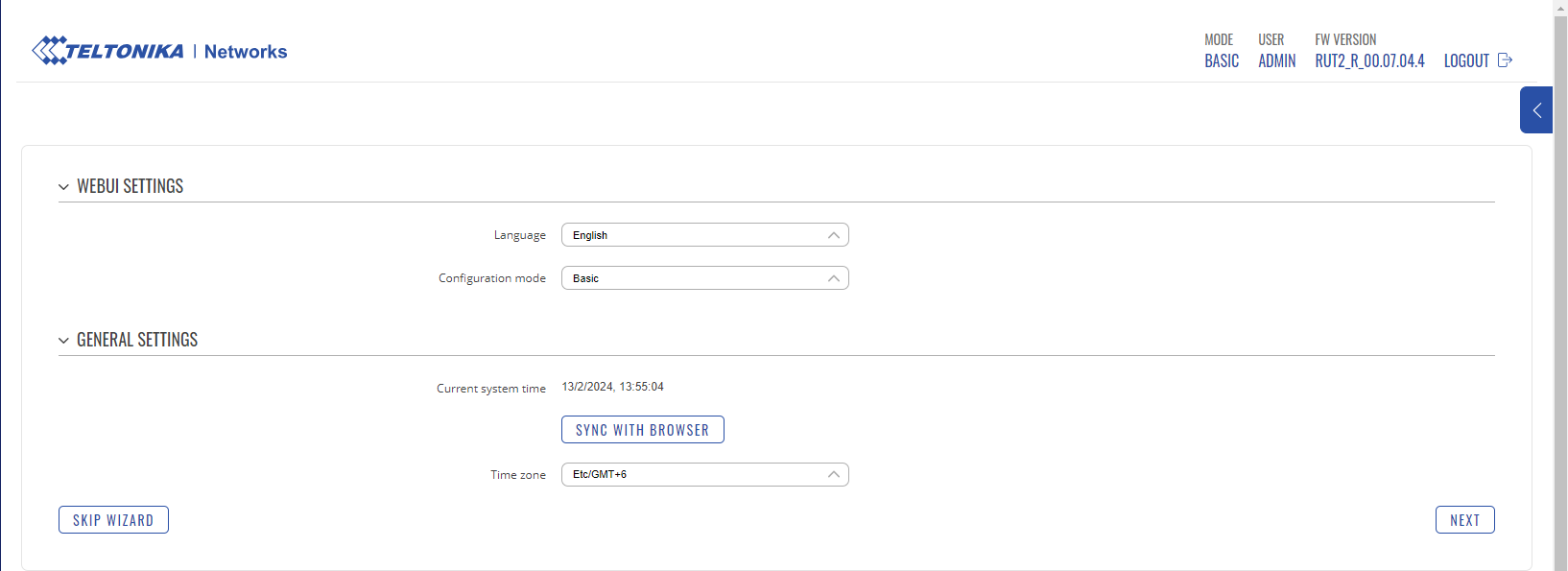
Step 2. Perform the initial configurations. Choose the language (the default language is English) and time zone (click on SYNC WITH BROWSER). Then, click on next.
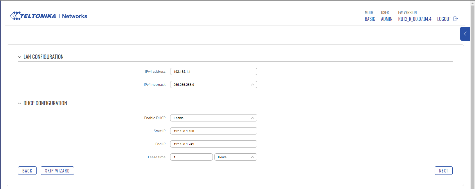
Configure the LAN port, management port, and DHCP server. The settings should be appropriate for your LAN subnet. LAN CONFIGURATION:
1. IPv4 address: IP address of the LAN port.
2. IPv4 netmask: Subnet mask.Netmask: Subnet mask. DHCP CONFIGURATION:
1. ENABLE DHCP: Enable.
2. Start IP: Initial range of IPs.
3. End IP: Final range of IPs.
4. Lease Time: IP release time.
Note: The subnet for the LAN network must be different from the WAN subnet. Click on next.
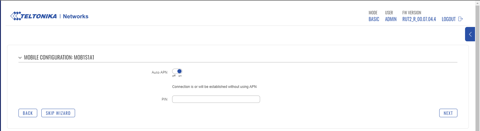
Leave it as default as shown in the image and click on next.
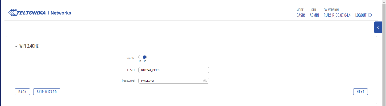
Configure the WI-FI network for administration. You can choose to click on next and keep the current network.
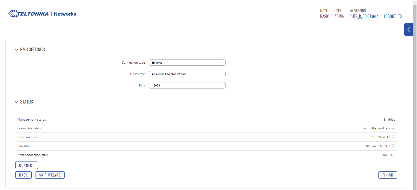
Finally, click on Finish.
Now, wait a few minutes and connect an Ethernet wire from your internet service provider to the WAN port for internet connection.
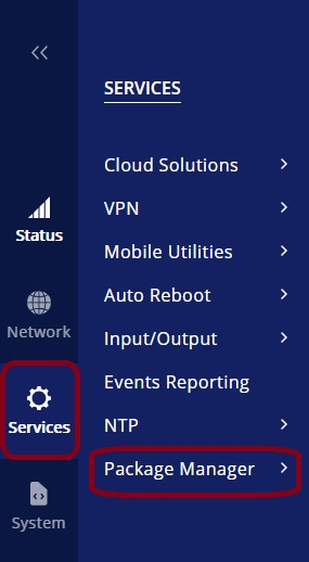
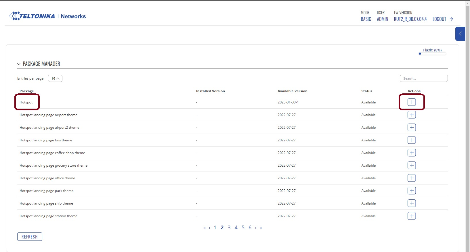
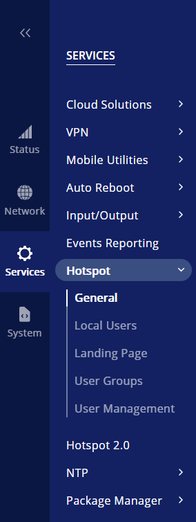
Step 3. Install the Hotspot library, go to the following menu.
Search for the word “hotspot” and click on the “+” button.
Click on “continue”.
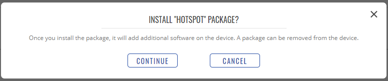
Finally, wait for the hotspot to be installed on the device.
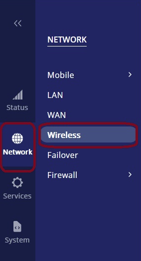
Step 4. Create a Wi-Fi network for the captive portal (hotspot). Go to the following menu. Note: You must be in advanced options, click on the following button.

Now, click on add.
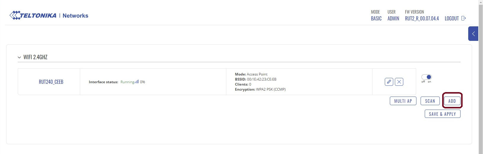
The settings should be as follows:
1. ESSID: Wi-Fi network name.
2. Network: - - No network - -
3. Password: Do not enter a password.
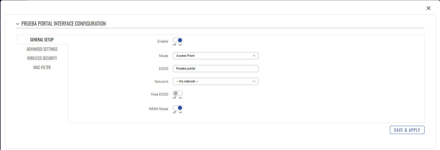
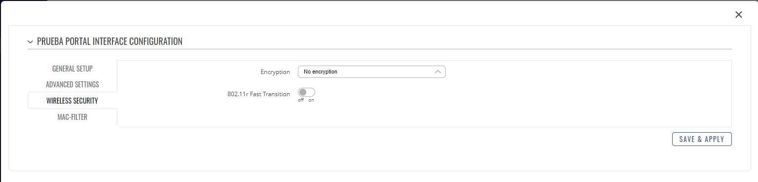
Click on "save and apply".
Note: Up to this point, your Wi-Fi network for the captive portal will be displayed, but you will not be able to connect.
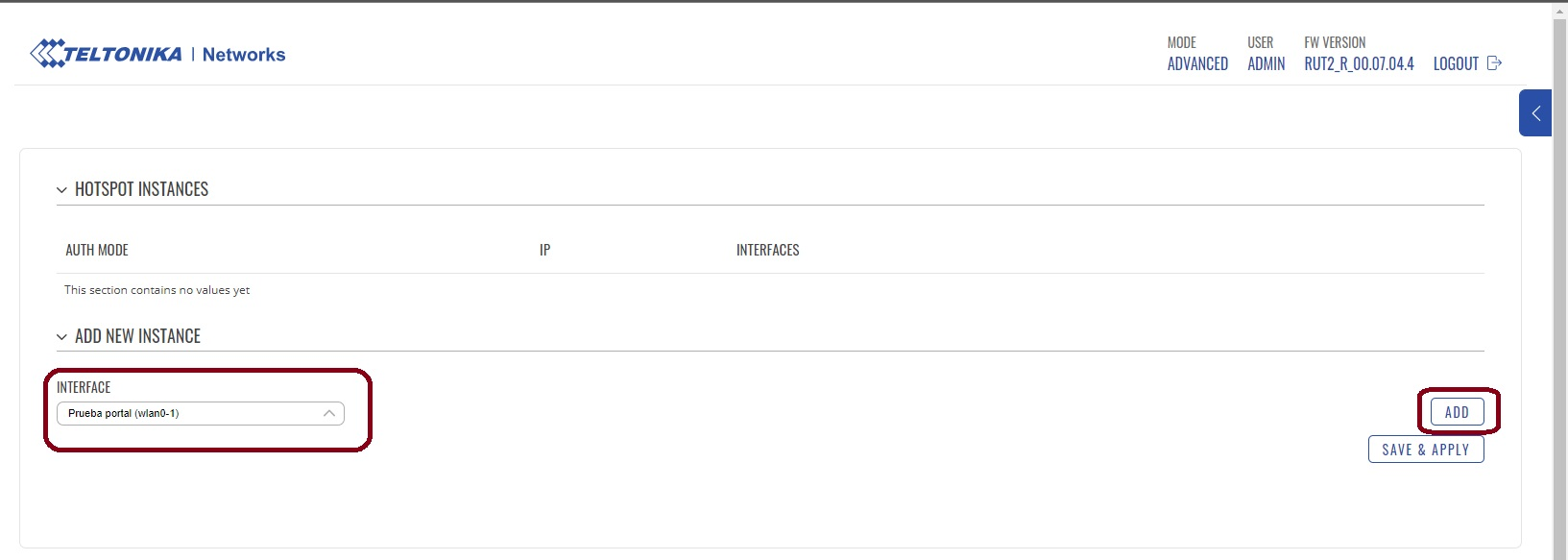
Step 5. Hotspot configuration. Go to the following menu.
Select the Wi-Fi network you created for the captive portal and click on add.
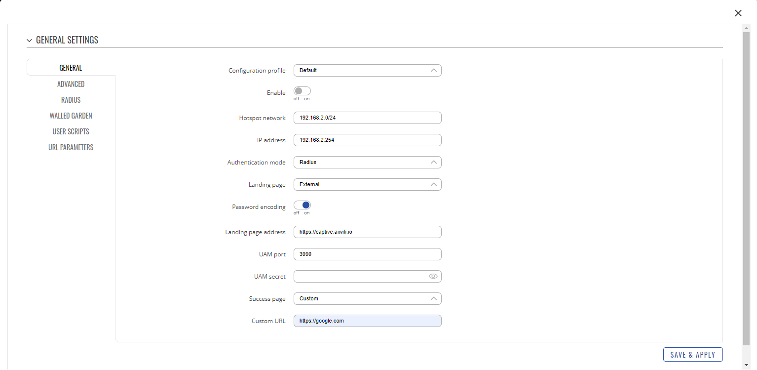
In “General”, configure the following:
1. Configuration profile: Default.
2. Authentication mode: Radius.
3. Landing Page: External.
4. Password encoding: On.
5. Landing Page address: https://captive.aiwifi.io
6. Success page: Custom.
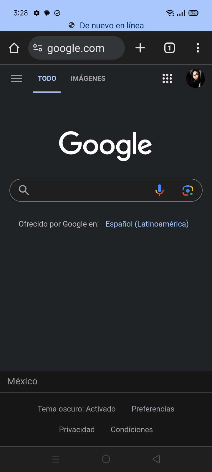
7. Custom URL: Page you want to redirect the user to.
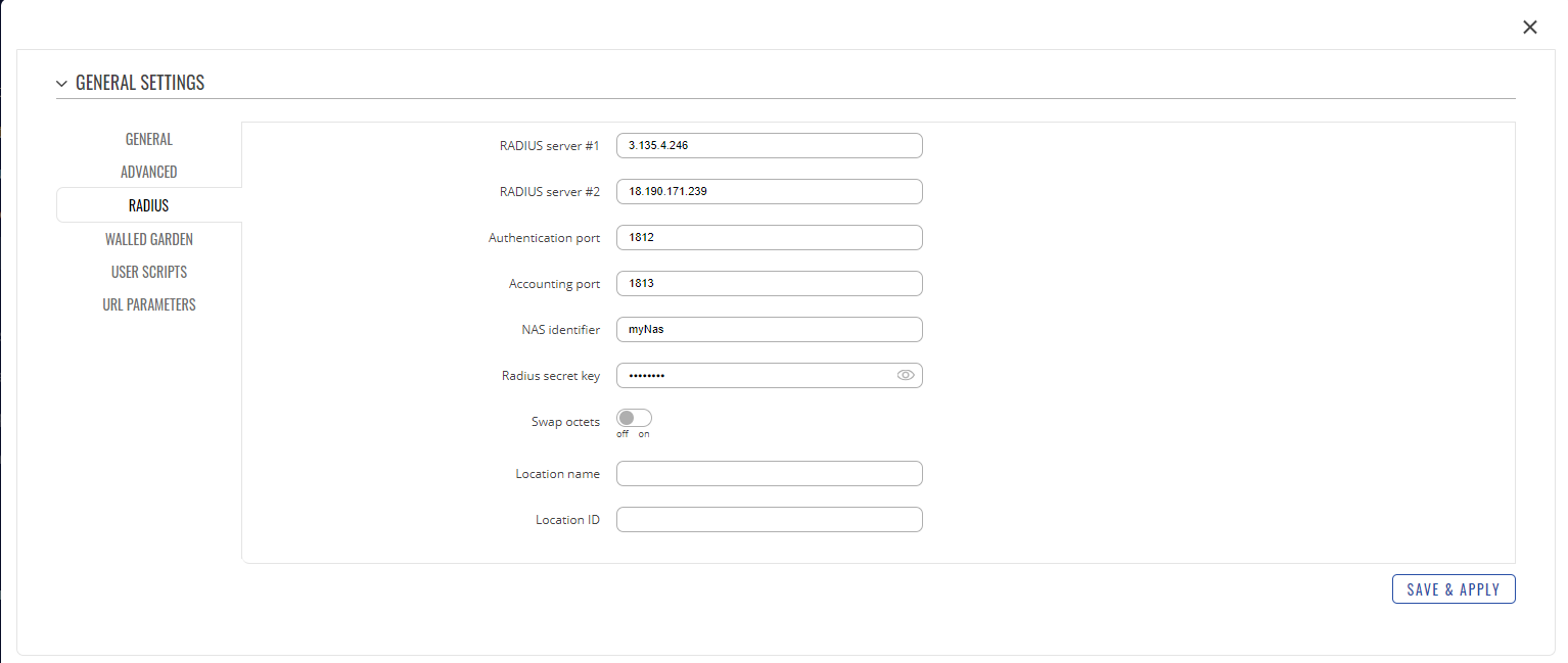
In the Radius tab, you should configure the following:
1. Radius server #1: 3.135.4.246
2. Radius server #2: 18.190.171.239
3. NAS identifier: myNas.
4. Radius secret key: (contact the support team
Now, in the “Walled Garden” tab, enter the following URLs that you can find at the following URL: https://help.aiwifi.io/en/category/configuration-manuals/article/basic-setup-information
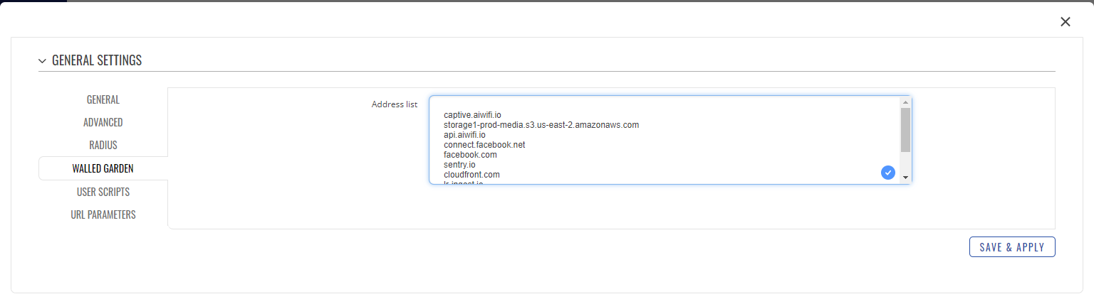
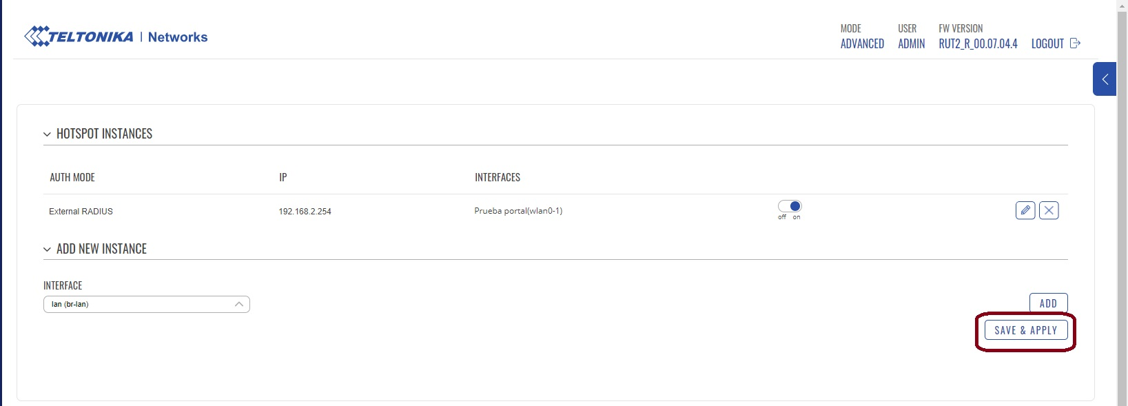
Finally, click on “Save and Apply”. Activate the captive portal by clicking on the following section and then click on “Save and Apply”.
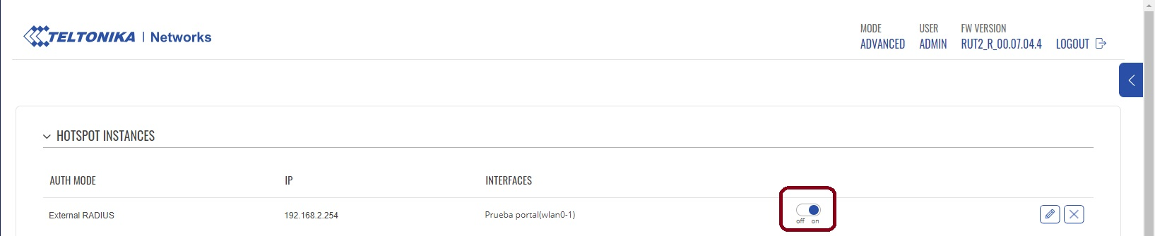
Note: Up to this point, the captive portal configuration is in correct operation, but it will not be displayed yet.
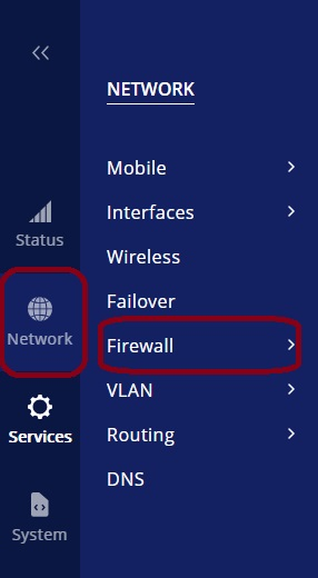
Step 6. Firewall Configuration. Go to the following menu:
Configure the hotspot zone, leave the settings as follows:
1. Input: Accept.
2. Output: Accept.
3. Output: Accept.
Click on Save and Apply.
Now, create a NAT rule for the hotspot. Go to the following menu.
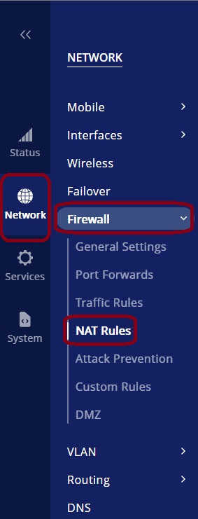
Now, you need to create a NAT rule for the hotspot to exit through the WAN port.
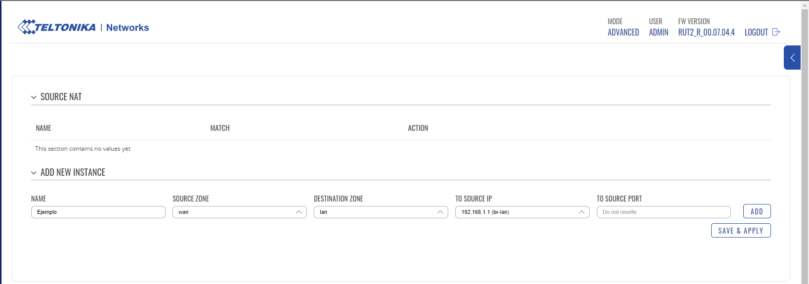
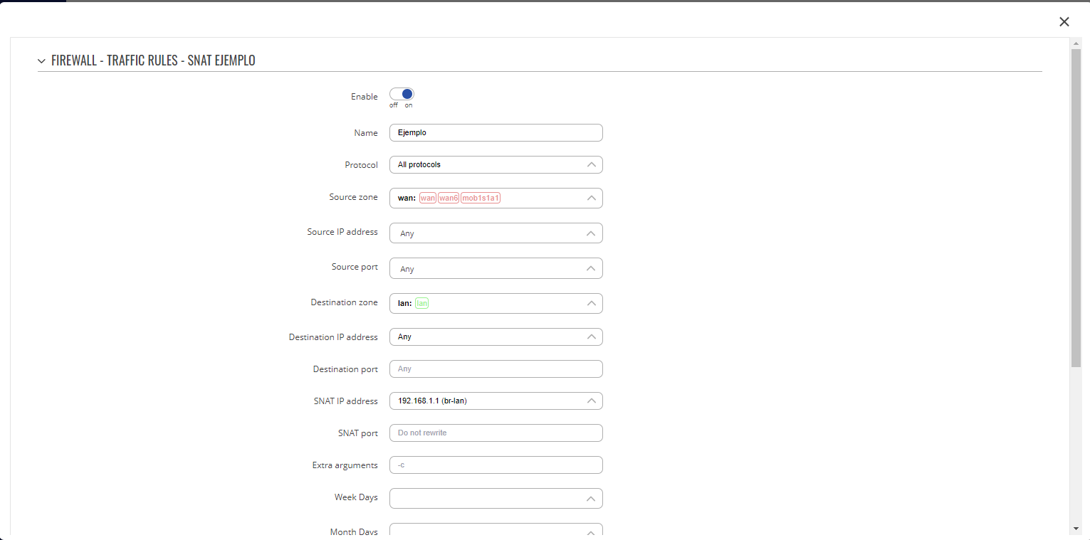
When you click on “add,” the following window will appear. Click on Save and Apply.

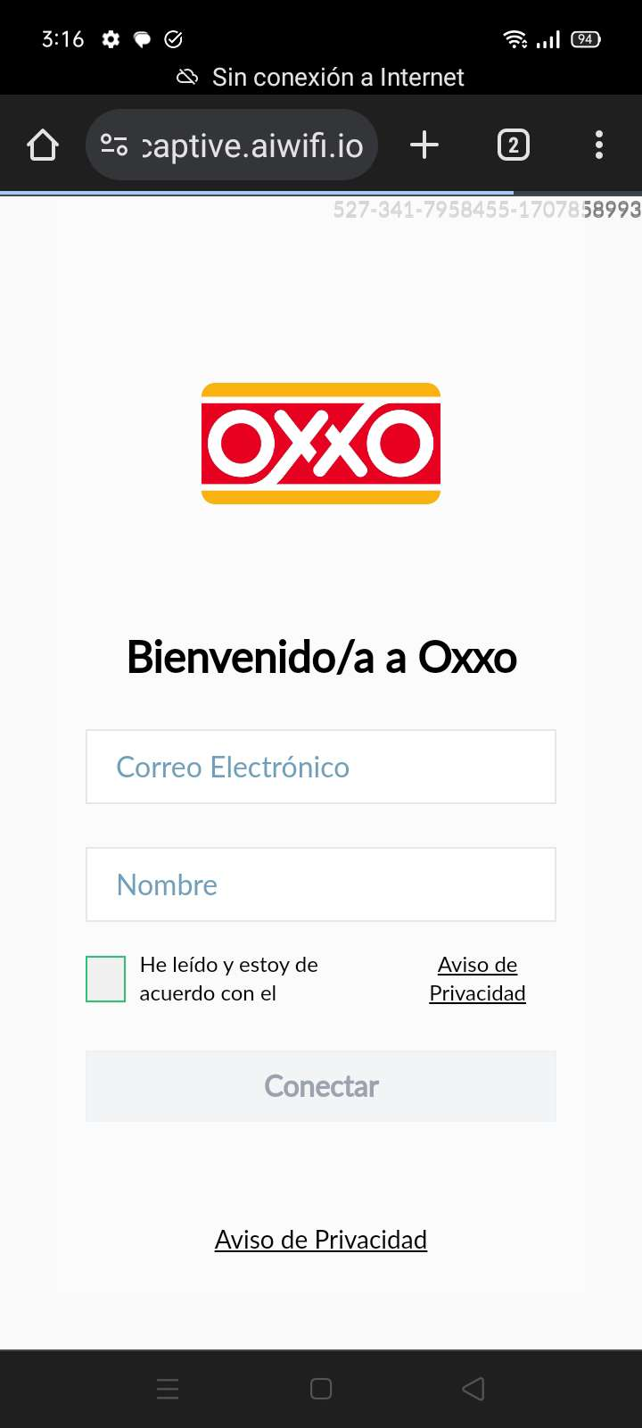
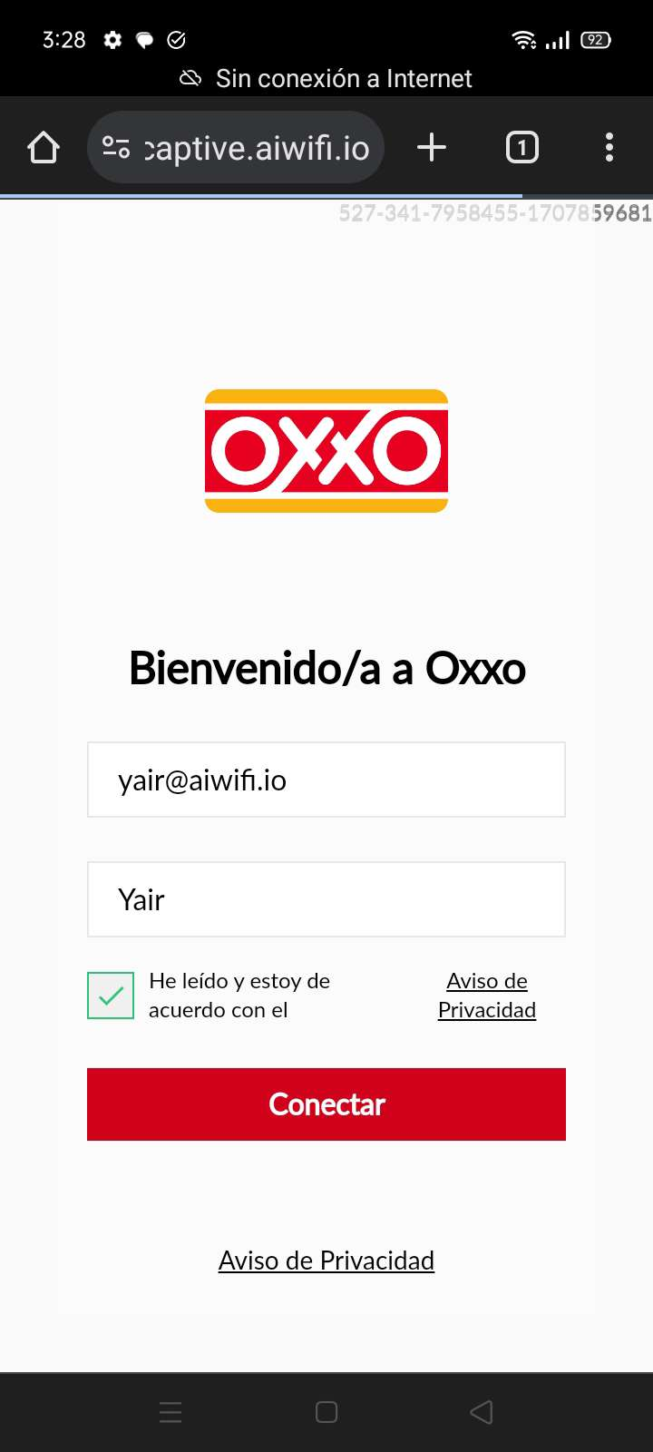
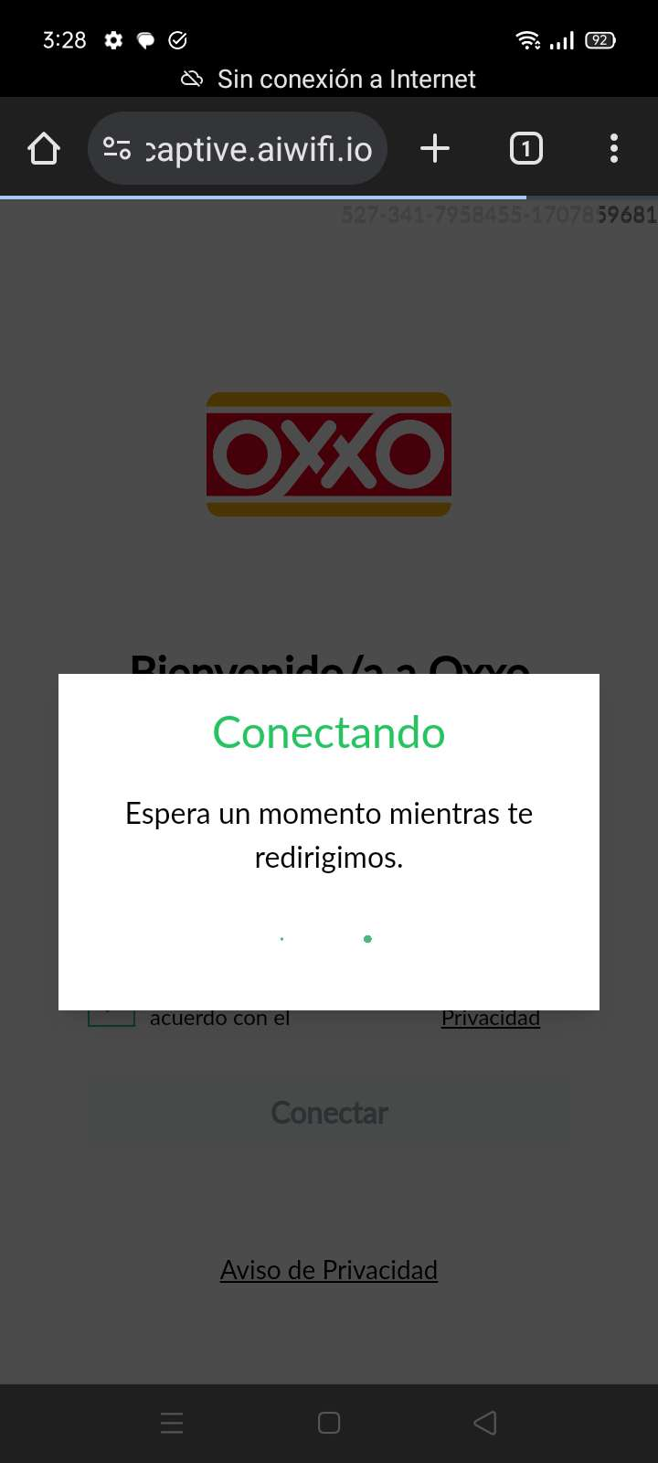
Once this is done, the captive portal will be visible as shown in the following image.